LEVEL 1- WIRED ROBOTICS
As name says ,In this type we use the medium of wires to Give Instructions to the Robot !!!
This is the most basic level . Even , most of the competitions held based on Level 1 Robotics!!!!
This is the most basic level . Even , most of the competitions held based on Level 1 Robotics!!!!
THINGS YOU NEED
CIRCUIT DIAGRAM


PROCEDURE
First thing , you need to do is , Connect 2 motors of one side in parallel as shown in below pic.
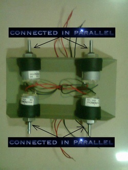
i.e. Red wire of first motor is connected with Red wire of Second motor of same side as shown in Above Diagram !!!!!Also Similar for Black wires!!!!!!
REMOTE CONNECTION
(CLICK THE PICTURE TO ZOOM THE IMAGE)
In this case ,
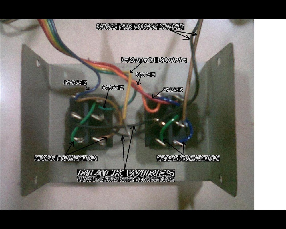
For switch of Left side
WIRE 1
WIRE 2
For switch of Right side
WIRE 3
WIRE 4
And, 5th wire is extra,,,
we have to cross connect these wires to the bottom part of the switch , The wires shown in the image by name "CROSS CONNECTION".
In the middle of the switch;In the above case, we have connected the wires for power supply to Right hand side's switch which further connected to the Left switch(As shown ,In the image by the name "BLACK WIRES").Also,Solder the all wires while finishing !
In this case ,
For switch of Left side
WIRE 1
WIRE 2
For switch of Right side
WIRE 3
WIRE 4
And, 5th wire is extra,,,
we have to cross connect these wires to the bottom part of the switch , The wires shown in the image by name "CROSS CONNECTION".
In the middle of the switch;In the above case, we have connected the wires for power supply to Right hand side's switch which further connected to the Left switch(As shown ,In the image by the name "BLACK WIRES").Also,Solder the all wires while finishing !
MOTOR CONNECTION
(CLICK THE PICTURE TO ZOOM THE IMAGE)
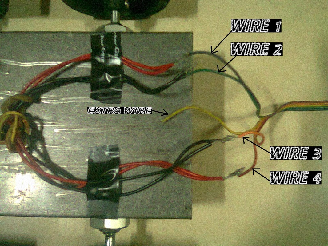
WIRE 1 and WIRE 2 of Left switch are connected to the upper 2 motors as shown in the image.
Also, WIRE 3 and WIRE 4 of Right switch are connected to the lower 2 motors (see the image).
(i.e One switch is connected to 2 motors of one side)
NOW,ADJUST THE WIRES TO MAKE COMFORTABLE DRIVING BY CHANGING THE POLARITIES
After that , Bind all wires together by tape.

